Wednesday, January 9, 2019

PROJECTION AUGMENTED MODEL

affiliate_link

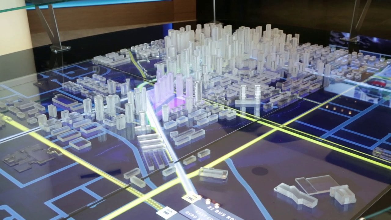
A projection augmented model (PA model): 

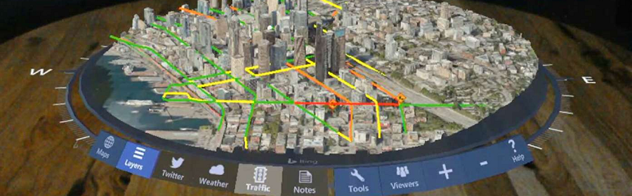
an element sometimes employed in virtual reality systems. It consists of a physical three-dimensional model onto which a computer image is projected to create a realistic looking object. Importantly, the physical model is the same geometric shape as the object that the PA model depicts.
affiliate_link
Spatially augmented reality (SAR) renders virtual objects directly within or on the user's physical space. A key benefit of SAR is that the user does not need to wear a head-mounted display. Instead, with the use of spatial displays, wide field of view and possibly high-resolution images of virtual objects can be integrated directly into the environment. For example, the virtual objects can be realized by using digital light projectors to paint 2D/3D imagery onto real surfaces, or by using built-in flat panel displays.

Real objects can be physically handled and naturally manipulated to be viewed from any direction, which is essential for ergonomic evaluation and provides a strong sense of palpability. Although simulated hap tic feedback devices enable some aspects of computer-generated objects to be touched, they cannot match this level of functionality. It is, therefore, unsurprising that physical objects are still used for many applications, such as product design. However, computer-generated objects have a key advantage; they provide a level of flexibility that cannot be matched by physical objects. Therefore, a display is needed that somehow joins the real physical world and computer-generated objects together, thus enabling them to be experienced simultaneously.
Tangible user interfaces (TUI) and augmented reality both aim to address this issue. TUI systems use real physical objects to both represent and also interact with computer-generated information. However, while TUIs create a physical link between real and computer-generated objects, they do not create the illusion that the computer-generated objects are actually in a user’s real environment. That is the aim of augmented reality.
affiliate_link
Unlike virtual reality (VR), which immerses a user in a computer-generated environment, augmented reality (AR) joins together physical and virtual spaces by creating the illusion that computer-generated objects are actually real objects in a user’s environment. Furthermore, head-mounted-display based AR and VR systems can directly incorporate physical objects. Thus, as a user reaches out to a computer-generated object that they can see, they touch an equivalent physical model that is placed at the same spatial location. Such systems enable the computer-generated visual appearance of the object to be dynamically altered, while the physical model provides hap tic feedback for the object’s underlying form. However, head-mounted-display based systems require users to wear equipment, which limits the number of people who can simultaneously use the display.
A variant of the AR paradigm that does not suffer from these limitations is spatially augmented reality. Spatially augmented reality displays project computer-generated information directly into the user’s environment. Although there are several possible display configurations, the most natural type is the projection augmented model.
A projection augmented model (PA model) consists of a physical three-dimensional model, onto which a computer image is projected to create a realistic looking object. Importantly, the physical model is the same geometric shape as the object that the PA model depicts. For example, the image projected onto the objects provides color and visual texture, which makes them appear to be made from different materials.
affiliate_link
PA models use a unique combination of physical objects and computer-generated information, and hence they inherit advantages from both. “The human interface to a physical model is the essence of ‘intuitive’. There are no widgets to manipulate, no sliders to move, and no displays to look through (or wear). Instead, we walk around objects, moving in and out to zoom, gazing and focusing on interesting components, all at very high visual, spatial, and temporal fidelity”. PA models combine the high level of intuitiveness of physical models with the flexibility and functionality of computer graphics, such as the ability to be quickly altered, animated, saved and updated (Jacucci, Oulasvirta, Psik, Salovaara & Wagner, 2005). Thus, a PA model essentially gives a physical form to a computer-generated object, which a user can touch and grasp with their bare hands. It is therefore unsurprising that user studies, which compared PA models to other Virtual and Augmented Reality displays, found PA models to be a natural and intuitive type of display (Nam & Lee, 2003; Stevens et al., 2002).
However, the PA model concept is not new. In fact, one of the first PA model type displays was created over twenty years ago when Naimark built the ‘Displacements’ art installation (Naimark, 1984) and more recently in the “Haunted Mansion” attraction in Disney World (Liljegren & Foster, 1990). At the time technology did not exist for a PA model to be much more than an artistic statement. However, given the technology available today and a little “unfettered imagination”, exploring novel projection displays is now “potentially boundless”.
Related image
The growth in PA model technology has been marked by the recent recreation of Naimark’s ‘Displacements’ installation at SIGGRAPH (Displacements, 2005). Specifically, new technology has been developed that semi-automates the process of both creating and aligning the physical model and projected image. This supports multiple projectors, which enables a PA model to be illuminated from every direction. Furthermore, powerful projectors (2000-3000 lumens) can be used to allow a PA model to be located in a well-lit room (Nam, 2005; Memory, Keller & Staplers, 2003). However, whilst this technology enables a PA model to be a viable and useful type of display, it does not address its main aim.
A PA model aims to create the illusion of actually being the object that it depicts. For example, when used for a product design application, it is important that a PA model provides a convincing perceptual impression of actually being the final product (Nam, 2006; Sakes, 2006; Verlinden, Horvath & Edelenbos, 2006; Keller & Sappers, 2001). Similarly, when used for a museum display application to create a replica of an artifact, a PA model aims to create the illusion of being the real artifact (Hirooka & Satio, 2006; Senckenberg Museum, 2006; Bimber, Gatesy, Witmer, Raskar & Encarnacao, 2002; Museum of London, 1999).

affiliate_link

SPIRITUAL MAPPING

affiliate_link

Spiritual warfare is the Christian concept of fighting:

against the work of preternatural evil forces. It is based on the biblical belief in evil spirits, or demons, that are said to intervene in human affairs in various ways. Various Christian groups have adopted practices to repel such forces, as based on their doctrine of Christian demonology. Prayer is a common form of spiritual warfare among Christians. Other practices may include exorcism, the laying on of hands, fasting, and anointing with oil. Jewish demonology escalated with the rise of Jewish pseudepigraphic writings of the 1st Century BCE, in particular with Enoch apocrypha. Jewish apocrypha initially influenced post-New Testament writings of the early fathers, which further defined Christian demonology.[citation needed] Thus followed literary works such as The Did ache, The Shepherd of Herm’s, Ignatius's epistle to the Ephesians, and Origen's Contra Cesium.

Mainstream Christianity typically acknowledges a belief in the reality (or ontological existence) of demons, fallen angels, the Devil in Christianity and Satan. In Christian evangelism, doctrines of demonology are influenced by interpretations of the New Testament, namely with the Gospels, in that dealing with spirits became a customary activity of Jesus' ministry. Mark states that "he traveled throughout Galilee, preaching in their synagogues and driving out demons" (Mark 1:39).
Exorcisms may be promoted by evangelists referring to Jesus comment, "If I drive out demons by the spirit of God, then the kingdom of God is upon you"

Evangelical Christian traditions believe that Satan and his minions exercise significant influence over this world and its power structures. A hostile realm in conflict with the kingdom of God is recorded in the Bible by the Apostle John, "the whole world is under the control of the evil one" (1 John 5:19) and by Jesus who referred to Satan as "the prince of this world"  which may point to the concept of Territorial Spirits.
affiliate_link
Paul elaborates on demonic hierarchy in Ephesians 6 where he also mentions, by way of metaphor, those qualities needed for defense against them. Two of those articles, the helmet of Salvation and the breastplate of Righteousness, are also mentioned in the book of Isaiah.
It is also believed that Satan occupies a temporal existence when the Apostle Paul refers to him as "the god of this age". Further, Paul's epistles focus on the Victory of Christ over principalities and powers. Evangelical interpretation has history divided into two eras: the present evil age and the age to come which supports the concept of the Second coming of Christ.

Imagery of spiritual warfare is displayed in the Book of Revelation when after the War in Heaven , the beasts and kings of the earth wage war against God's people, and a final battle ensues with Satan and the nations of the earth against God himself.
Christian practices of spiritual warfare vary throughout Christianity. The development of specific spiritual warfare techniques has also generated many discussions in the Christian mission’s community. Critical exchanges of views may be found in periodicals like the Evangelical Missions Quarterly (such as in volume 31, number 2 published in 1995), and in conferences sponsored by the Evangelical Missions Society. In 2000, an international collaborative attempt was made by evangelicals and charismatics in the Lausanne Committee for World Evangelization to reach some common agreement about spiritual warfare. The conference gathered in Nairobi, Kenya, and yielded a consultation document as well as many technical papers published as the book Deliver Us from Evil. Spiritual warfare has also been practiced by non-Christians and in non-Christian countries. According to the Christian Broadcasting Network commentator Carl Moeller, spiritual warfare is practiced even in North Korea, a country that has been described as the most dangerous place on earth to be Christian. Non-Christian media reported on the African spiritual warrior Pastor Thomas Muthee visit to America who prayed over a 2008 presidential candidate. The Nigerian Tribune, the oldest surviving private newspaper in Nigeria, has published articles calling for the need for spiritual warfare. In the case of Haiti, American televangelist Pat Robertson and others blamed the earthquake of 2010 on demons, and called for Christians to increase spiritual warfare prayer.

affiliate_link
Expositors of spiritual warfare include Jessie Penn-Lewis, who published the Pentecostal 1903 book, War on the Saints, prolific author Pastor Win Worley started publishing his Hosts of Hell series in 1976, and Kurt E. Koch published Occult ABC, which all contain elements of the concept of spiritual warfare, if not explicitly using the expression. In 1991, C. Peter Wagner published Confronting the Powers: How the New Testament Church Experienced the Power of Strategic-Level Spiritual Warfare and edited Territorial Spirits. In 1992, Dr. Ed Murphy wrote a modern 600-page book on the subject, “The Handbook of Spiritual Warfare“, from the point of view of deliverance ministry. Laws of Deliverance, From Proverbs, 1980, 1983, 1995, 2000, 2003, written by Marilyn A. Ellsworth, is another important Biblical work of authority, as is her book ICBM Spiritual Warfare, God's Unbeatable Plan. Other notable expositions on spiritual warfare were written by Pastor Win Worley, Mark Bubeck, and Neil Anderson.
Image result for SPIRITUAL MAPPING
Pope John Paul II stated, “‘Spiritual combat’… is a secret and interior art, an invisible struggle in which monks engage every day against the temptations”.
In modern times the views of individual Roman Catholics have tended to divide into traditional and more modern understandings of the subject. An example of a more modern view of the demonic is found in the work of the Dominican scholar Richard Woods' The Devil.
The traditional outlook is represented by Father Gabriele Abort who has written three books on his personal experiences as an exorcist for the Vatican: An Exorcist Tells His Story, and An Exorcist: More Stories, and An Exorcist Explains the Demonic: The Antics of Satan and His Army of Fallen Angels. Francis MacNutt, who was a priest within the Roman Catholic Charismatic Movement, has also addressed the subject of the demonic in his writings about healing.
affiliate_link
The practice of exorcism was also known among the first generation of teachers and pastors in the Lutheran Reformation. Johannes Bugenhagen was the pastor of the Wittenberg town church and officiated at Martin Luther's wedding. In a letter addressed to Luther and Melanchthon dated November 1530, Pomerania recounted his experience of dealing with a young girl who showed signs of demon possession. Pomerania' method involved counseling the girl concerning her previous baptismal vows, he invoked the name of Christ and prayed with her. (Letter reproduced in Montgomery, Principalities and Powers).

affiliate_link

MIND MAP

affiliate_link A mind map is a diagram used to visually organize information. A mind map is hierarchical and shows relationships among pieces of the whole. It is often created around a single concept, drawn as an image in the center of a blank page, to which associated representations of ideas such as images, words and parts of words are added. Major ideas are connected directly to the central concept, and other ideas branch out from those major ideas.

Mind maps can also be drawn by hand, either as "rough notes" during a lecture, meeting or planning session, for example, or as higher quality pictures when more time is available. Mind maps are considered to be a type of spider diagram. A similar concept in the 1970s was "idea sun bursting".
affiliate_link
Although the term "mind map" was first popularized by British popular psychology author and television personality Tony Buzan, the use of diagrams that visually "map" information using branching and radial maps traces back centuries. These pictorial methods record knowledge and model systems, and have a long history in learning, brainstorming, memory, visual thinking, and problem solving by educators, engineers, psychologists, and others. Some of the earliest examples of such graphical records were developed by Porphyry of Tyros, a noted thinker of the 3rd century, as he graphically visualized the concept categories of Aristotle. Philosopher Ramon Lull (1235–1315) also used such techniques.
affiliate_link
The semantic network was developed in the late 1950s as a theory to understand human learning and developed further by Allan M. Collins and M. Ross Quill and during the early 1960s. Mind maps are similar in radial structure to concept maps, developed by learning experts in the 1970s, but differ in that the former are simplified by focusing around a single central key concept.
Buzan's specific approach, and the introduction of the term "mind map", arose during a 1974 BBC TV series he hosted, called Use Your Head. In this show, and companion book series, Buzan promoted his conception of radial tree, diagramming key words in a colorful, radiant, tree-like structure.
Buzan says the idea was inspired by Alfred Korzybski's general semantics as popularized in science fiction novels, such as those of Robert A. Heinlein and A. E. van Vogt. He argues that while "traditional" outlines force readers to scan left to right and top to bottom, readers actually tend to scan the entire page in a non-linear fashion. Buzan's treatment also uses then-popular assumptions about the functions of cerebral hemispheres in order to explain the claimed increased effectiveness of mind mapping over other forms of note making.
Buzan suggests the following guidelines for creating mind maps:
Start in the center with an image of the topic, using at least 3 colors.
Use images, symbols, codes, and dimensions throughout your mind map.
Select keywords and print using upper or lower case letters.
affiliate_link
Each word/image is best alone and sitting on its own line.
The lines should be connected, starting from the central image. The lines become thinner as they radiate out from the center.
Make the lines the same length as the word/image they support.
Use multiple colors throughout the mind map, for visual stimulation and also for encoding or grouping.
Develop your own personal style of mind mapping.
Use emphasis and show associations in your mind map.
Keep the mind map clear by using radial hierarchy or outlines to embrace your branches.
As with other diagramming tools, mind maps can be used to generate, visualize, structure, and classify ideas, and as an aid to studying and organizing information, solving problems, making decisions, and writing.
Mind maps have many applications in personal, family, educational, and business situations, including note taking, brainstorming (wherein ideas are inserted into the map radially around the center node, without the implicit prioritization that comes from hierarchy or sequential arrangements, and wherein grouping and organizing is reserved for later stages), summarizing, as a mnemonic technique, or to sort out a complicated idea. Mind maps are also promoted as a way to collaborate in color pen creativity sessions.
In addition to these direct use cases, data retrieved from mind maps can be used to enhance several other applications; for instance, expert search systems, search engines and search and tag query recommender. To do so, mind maps can be analyzed with classic methods of information retrieval to classify a mind map's author or documents that are linked from within the mind map.
Concept maps: Mind maps differ from concept maps in that mind maps focus on only one word or idea, whereas concept maps connect multiple words or ideas. Also, concept maps typically have text labels on their connecting lines/arms. Mind maps are based on radial hierarchies and tree structures denoting relationships with a central governing concept, whereas concept maps are based on connections between concepts in more diverse patterns. However, either can be part of a larger personal knowledge base system.
Image result for MIND MAP
Cunningham (2005) conducted a user study in which 80% of the students thought "mind mapping helped them understand concepts and ideas in science". Other studies also report some subjective positive effects on the use of mind maps. Positive opinions on their effectiveness, however, were much more prominent among students of art and design than in students of computer and information technology, with 62.5% vs. 34% (respectively) agreeing that they were able to understand concepts better with mind mapping software. Farr and, Hussain, and Hennessy (2002) found that spider diagrams
affiliate_link
(Similar to concept maps) had limited, but significant, impact on memory recall in undergraduate students (a 10% increase over baseline for a 600-word text only) as compared to preferred study methods (a 6% increase over baseline). This improvement was only robust after a week for those in the diagram group and there was a significant decrease in motivation compared to the subjects' preferred methods of note taking. A Meta study about concept mapping concluded that concept mapping is more effective than "reading text passages, attending lectures, and participating in class discussions". The same study also concluded that concept mapping is slightly more effective "than other constructive activities such as writing summaries and outlines". However, results were inconsistent, with the authors noting "significant heterogeneity was found in most subsets". In addition, they concluded that low-ability students may benefit more from mind mapping than high-ability students.

TEXTURE MAPPING

affiliate_link

Texture mapping is a method for defining:

high frequency detail, surface texture, or color information on a computer-generated graphic or 3D model. Its application to 3D graphics was pioneered by Edwin Cat mull in 1974. Texture mapping originally referred to a method (now more accurately called diffuse mapping) that simply wrapped and mapped pixels from a texture to a 3D surface. In recent decades the advent of multi-pass rendering and complex mapping such as height mapping, bump mapping, normal mapping, displacement mapping, reflection mapping, specula mapping, mipmaps, occlusion mapping, and many other variations on the technique.


(controlled by a materials system) have made it possible to simulate near-photorealism in real time by vastly reducing the number of polygons and lighting calculations needed to construct a realistic and functional 3D scene. A texture map is an image applied (mapped) to the surface of a shape or polygon. This may be a bitmap image or a procedural texture. They may be stored in common image file formats, referenced by 3d model formats or material definitions, and assembled into resource bundles. They may have 1-3 dimensions, although 2 dimensions are most common for visible surfaces. For use with modern hardware, texture map data may be stored in swizzle or tiled orderings to improve cache coherency. Rendering APIs typically manage texture map resources (which may be located in device memory) as buffers or surfaces, and may allow 'render to texture' for additional effects such as post processing, environment mapping.
They usually contain RGB color data (either stored as direct color, compressed formats, or indexed color), and sometimes an additional channel for alpha blending (RGBA) especially for billboards and decal overlay textures. It is possible to use the alpha channel (which may be convenient to store in formats parsed by hardware) for other uses such as secularity.
Multiple texture maps (or channels) may be combined for control over secularity, normal’s, displacement, or subsurface scattering e.g. for skin rendering.
affiliate_link
Multiple texture images may be combined in texture atlases or array textures to reduce state changes for modern hardware. (They may be considered a modern evolution of tile map graphics). Modern hardware often supports cube map textures with multiple faces for environment mapping.
Texture maps may be acquired by scanning/digital photography, authored in image manipulation software such as GIMP, Photoshop, or painted onto 3D surfaces directly in a 3D paint tool such as Mud box or zbrush.
affiliate_link
This process is akin to applying patterned paper to a plain white box. Every vertex in a polygon is assigned a texture coordinate (which in the 2d case is also known as UV coordinates). This may be done through explicit assignment of vertex attributes, manually edited in a 3D modeling package through UV unwrapping tools. It is also possible to associate a procedural transformation from 3d space to texture space with the material. This might be accomplished via planar projection or, alternatively, cylindrical or spherical mapping. More complex mappings may consider the distance along a surface to minimize distortion. These coordinates are interpolated across the faces of polygons to sample the texture map during rendering. Textures may be repeated or mirrored to extend a finite rectangular bitmap over a larger area, or they may have a one-to-one unique "injective" mapping from every piece of a surface (which is important for render mapping and light mapping, also known as baking).
affiliate_link
Texture mapping maps the model surface (or screen space during rasterization) into texture space; in this space, the texture map is visible in its undistorted form. UV unwrapping tools typically provide a view in texture space for manual editing of texture coordinates. Some rendering techniques such as subsurface scattering may be performed approximately by texture-space operations.
Multitexturing is the use of more than one texture at a time on a polygon. For instance, a light map texture may be used to light a surface as an alternative to recalculating that lighting every time the surface is rendered. Micro textures or detail textures are used to add higher frequency details, and dirt maps may add weathering and variation; this can greatly reduce the apparent periodicity of repeating textures. Modern graphics may use more than 10 layers, which are combined using shades, for greater fidelity. Another multitexture technique is bump mapping, which allows a texture to directly control the facing direction of a surface for the purposes of its lighting calculations; it can give a very good appearance of a complex surface (such as tree bark or rough concrete) that takes on lighting detail in addition to the usual detailed coloring. Bump mapping has become popular in recent video games, as graphics hardware has become powerful enough to accommodate it in real-time.
The way that samples (e.g. when viewed as pixels on the screen) are calculated from the Texel’s (texture pixels) is governed by texture filtering. The cheapest method is to use the nearest-neighbor interpolation, but bilinear interpolation or trilinear interpolation between mipmaps are two commonly used alternatives which reduce aliasing or jaggiest. In the event of a texture coordinate being outside the texture, it is either clamped or wrapped. Anisotropic filtering better eliminates directional artifacts’ when viewing textures from oblique viewing angles.
Image result for TEXTURE MAPPING
As an optimization, it is possible to render detail from a high resolution model or expensive process (such as global illumination) into a surface texture (possibly on a low resolution model). This is also known as render mapping. This technique is most commonly used for light mapping but may also be used to generate normal maps and displacement maps. Some video games (e.g. Messiah) have used this technique. The original Quake software engine used on-the-fly baking to combine light maps and color texture-maps ("surface caching").
Baking can be used as a form of level of detail generation, where a complex scene with many different elements and materials may be approximated by a single element with a single texture which is then algorithmically reduced for lower rendering cost and fewer draw calls. It is also used to take high detail models from 3D sculpting software and point cloud scanning and approximate them with meshes more suitable for real-time rendering.
affiliate_link

MAP SCALE FACTOR

affiliate_link

The scale of a map is the ratio of a distance:

 on the map to the corresponding distance on the ground. This simple concept is complicated by the curvature of the Earth's surface, which forces scale to vary across a map. Because of this variation, the concept of scale becomes meaningful in two distinct ways. The first way is the ratio of the size of the generating globe to the size of the Earth. The generating globe is a conceptual model to which the Earth is shrunk and from which the map is projected.

The ratio of the Earth's size to the generating globe's size is called the nominal scale (= principal scale = representative fraction). Many maps state the nominal scale and may even display a bar scale (sometimes merely called a 'scale') to represent it. The second distinct concept of scale applies to the variation in scale across a map. It is the ratio of the mapped point's scale to the nominal scale. In this case 'scale' means the scale factor (= point scale = particular scale).
If the region of the map is small enough to ignore Earth's curvature—a town plan, for example—then a single value can be used as the scale without causing measurement errors. In maps covering larger areas, or the whole Earth, the map's scale may be less useful or even useless in measuring distances. The map projection becomes critical in understanding how scale varies throughout the map. When scale varies noticeably, it can be accounted for as the scale factor. Tissot's indicatrix is often used to illustrate the variation of point scale across a map.
The foundations for quantitative map scaling go back to ancient China with textual evidence that the idea of map scaling was understood by the second century BC. Ancient Chinese surveyors and cartographers had ample technical resources used to produce maps such as counting rods, carpenter's square's, plumb lines, compasses for drawing circles, and sighting tubes for measuring inclination. Reference frames postulating a nascent coordinate system for identifying locations were hinted by ancient Chinese astronomers that divided the sky into various sectors or lunar lodges.
affiliate_link
The Chinese cartographer and geographer Pei Xiu of the Three Kingdoms period created a set of large-area maps that were drawn to scale. He produced a set of principles that stressed the importance of consistent scaling, directional measurements, and adjustments in land measurements in the terrain that was being mapped.
Map scales may be expressed in words (a lexical scale), as a ratio, or as a fraction. Examples are:
'One centimeter to one hundred meters’    or    1:10,000   or    1/10,000
'One inch to one mile'    or    1:63,360    or    1/63,360
'One centimeter to one thousand kilometers’   or   1:100,000,000    or    1/100,000,000.  (The ratio would usually be abbreviated to 1:100M)
In addition to the above many maps carry one or more (graphical) bar scales. For example, some modern British maps have three bar scales, one each for kilometers, miles and nautical miles.
A lexical scale in a language known to the user may be easier to visualize than a ratio: if the scale is an inch to two miles and the map user can see two villages that are about two inches apart on the map, then it is easy to work out that the villages are about four miles apart on the ground.
affiliate_link
A lexical scale may cause problems if it expressed in a language that the user does not understand or in obsolete or ill-defined units. For example, a scale of one inch to a furlong (1:7920) will be understood by many older people in countries where Imperial units used to be taught in schools. But a scale of one pouce to one league may be about 1:144,000, depending on the cartographer's choice of the many possible definitions for a league, and only a minority of modern users will be familiar with the units used.
A map is classified as small scale or large scale or sometimes medium scale. Small scale refers to world maps or maps of large regions such as continents or large nations. In other words, they show large areas of land on a small space. They are called small scale because the representative fraction is relatively small.
Large scale maps show smaller areas in more detail, such as county maps or town plans might. Such maps are called large scale because the representative fraction is relatively large. For instance a town plan, which is a large scale map, might be on a scale of 1:10,000, whereas the world map, which is a small scale map, might be on a scale of 1:100,000,000.
Related image
Mapping large areas causes noticeable distortions because it significantly flattens the curved surface of the earth. How distortion gets distributed depends on the map projection. Scale varies across the map, and the stated map scale is only an approximation. This is discussed in detail below.
The region over which the earth can be regarded as flat depends on the accuracy of the survey measurements. If measured only to the nearest meter, then curvature of the earth is undetectable over a meridian distance of about 100 kilometers (62 mi) and over an east-west line of about 80 km (at a latitude of 45 degrees). If surveyed to the nearest 1 millimeter (0.039 in), then curvature is undetectable over a meridian distance of about 10 km and over an east-west line of about 8 km. affiliate_link
Thus a plan of New York City accurate to one meter or a building site plan accurate to one millimeter would both satisfy the above conditions for the neglect of curvature. They can be treated by plane surveying and mapped by scale drawings in which any two points at the same distance on the drawing are at the same distance on the ground. True ground distances are calculated by measuring the distance on the map and then multiplying by the inverse of the scale fraction or, equivalently, simply using dividers to transfer the separation between the points on the map to a bar scale on the map.

affiliate_link

MAP PROJECTION

affiliate_link

A map projection is a systematic:

transformation of the latitudes and longitudes of locations from the surface of a sphere or an ellipsoid into locations on a plane. Maps cannot be created without map
affiliate_link
Projections. All map projections necessarily distort the surface in some fashion. Depending on the purpose of the map, some distortions are acceptable and others are not; therefore, different map projections exist in order to preserve some properties of the sphere-like body at the expense of other properties. There is no limit to the number of possible map projections.

More generally, the surfaces of planetary bodies can be mapped even if they are too irregular to be modeled well with a sphere or ellipsoid; see below. Even more generally, projections are a subject of several pure mathematical fields, including differential geometry, projective geometry, and manifolds. However, "map projection" refers specifically to a cartographic projection.
Maps can be more useful than globes in many situations: they are more compact and easier to store; they readily accommodate an enormous range of scales; they are viewed easily on computer displays; they can facilitate measuring properties of the region being mapped; they can show larger portions of the Earth's surface at once, and they are cheaper to produce and transport. These useful traits of maps motivate the development of map projections.
affiliate_link
However, Carl Friedrich Gauss's Theorem Egregious proved that a sphere's surface cannot be represented on a plane without distortion. The same applies to other reference surfaces used as models for the Earth, such as oblate spheroids, ellipsoids, and geoids. Since any map projection is a representation of one of those surfaces on a plane, all map projections distort. Every distinct map projection distorts in a distinct way. The study of map projections is the characterization of these distortions.
Projection is not limited to perspective projections, such as those resulting from casting a shadow on a screen, or the rectilinear image produced by a pinhole camera on a flat film plate. Rather, any mathematical function transforming coordinates from the curved surface to the plane is a projection. Few projections in actual use are perspective.
For simplicity, most of this article assumes that the surface to be mapped is that of a sphere. In reality, the Earth and other large celestial bodies are generally better modeled as oblate spheroids, whereas small objects such as asteroids often have irregular shapes. These other surfaces can be mapped as well. Therefore, more generally, a map projection is any method of "flattening" a continuous curved surface onto a plane.
Many properties can be measured on the Earth's surface independent of its geography. Some of these properties are:
Area
Shape
Direction
Bearing
Distance
Scale
Map projections can be constructed to preserve at least one of these properties, though only in a limited way for most. Each projection preserves, compromises, or approximates basic metric properties in different ways. The purpose of the map determines which projection should form the base for the map. Because many purposes exist for maps, a diversity of projections has been created to suit those purposes.
Another consideration in the configuration of a projection is its compatibility with data sets to be used on the map. Data sets are geographic information; their collection depends on the chosen datum (model) of the Earth. Different datum’s assign slightly different coordinates to the same location, so in large scale maps, such as those from national mapping systems, it is important to match the datum to the projection. The slight differences in coordinate assignation between different datums are not a concern for world maps or other vast territories, where such differences get shrunk to imperceptibility.
The classical way of showing the distortion inherent in a projection is to use Tissot's indicatrix. For a given point, using the scale factor h along the meridian, the scale factor k along the parallel, and the angle θ′ between them, Nicolas Tissot described how to construct an ellipse that characterizes the amount and orientation of the components of distortion: 147–149 By spacing the ellipses regularly along the meridians and parallels, the network of indicatrices shows how distortion varies across the map.
The creation of a map projection involves two steps:
affiliate_link
Selection of a model for the shape of the Earth or planetary body (usually choosing between a sphere and ellipsoid). Because the Earth's actual shape is irregular, information is lost in this step.
Transformation of geographic coordinates (longitude and latitude) to Cartesian (x, y) or polar plane coordinates. In large-scale maps, Cartesian coordinates normally have a simple relation to eastings and northing’s defined as a grid superimposed on the projection. In small-scale maps, easting and northing’s are not meaningful, and grids are not superimposed.
Some of the simplest map projections are literal projections, as obtained by placing a light source at some definite point relative to the globe and projecting its features onto a specified surface. This is not the case for most projections, which are defined only in terms of mathematical formulae that have no direct geometric interpretation. However, picturing the light source-globe model can be helpful in understanding the basic concept of a map projection
A surface that can be unfolded or unrolled into a plane or sheet without stretching, tearing or shrinking is called a developable surface. The cylinder, cone and the plane are all developable surfaces. The sphere and ellipsoid do not have developable surfaces, so any projection of them onto a plane will have to distort the image. (To compare, one cannot flatten an orange peel without tearing and warping it.)
Related image
One way of describing a projection is first to project from the Earth's surface to a developable surface such as a cylinder or cone, and then to unroll the surface into a plane. While the first step inevitably distorts some properties of the globe, the developable surface can then be unfolded without further distortion.
Once a choice is made between projecting onto a cylinder, cone, or plane, the aspect of the shape must be specified. The aspect describes how the developable surface is placed relative to the globe: it may be normal (such that the surface's axis of symmetry coincides with the Earth's axis), transverse (at right angles to the Earth's axis) or oblique (any angle in between).
The developable surface may also be either tangent or secant to the sphere or ellipsoid.

affiliate_link

HUMAN CONNECTOME PROJECT

affiliate_link
The Human Connectome Project (HCP) is a five-year project sponsored by sixteen components of the National Institutes of Health, split between two consortia of research institutions. The project was launched in July 2009 as the first of three Grand Challenges of the NIH's Blueprint for Neuroscience Research. On September 15, 2010, the NIH announced that it would award two grants: $30 million over five years to a consortium led by Washington University in Saint Louis and the University of Minnesota, with strong contributions from Oxford University (FMRIB) and $8.5 million over three years to a consortium led by Harvard University, Massachusetts General Hospital and the University of California Los Angeles.

The goal of the Human Connectome Project is to build a "network map" (connectome) that will shed light on the anatomical and functional connectivity within the healthy human brain, as well as to produce a body of data that will facilitate research into brain disorders such as dyslexia, autism, Alzheimer's disease, and schizophrenia.
As of November 16, 2018, the project has yet to be officially declared complete.
The WU-Minn-Oxford consortium developed improved MRI instrumentation, image acquisition and image analysis methods for mapping the connectivity in the human brain at spatial resolutions significantly better than previously available; using these methods, WI-Minn-Oxford consortium collected a large amount of MRI and behavioral data on 1,200 healthy adults — twin pairs and their siblings from 300 families - using a special 3 Tesla MRI instrument. In addition, it scanned 184 subjects from this pool at 7 Tesla, with higher spatial resolution. The data are being analyzed to show the anatomical and functional connections between parts of the brain for each individual, and will be related to behavioral test data. Comparing the connectomes and genetic data of genetically identical twins with fraternal twins will reveal the relative contributions of genes and environment in shaping brain circuitry and pinpoint relevant genetic variation. The maps will also shed light on how brain networks are organized.
affiliate_link
Using a combination of non-invasive imaging technologies, including resting-state fMRI and task-based functional MRI, MEG and EEG, and diffusion MRI, the WU-Minn will be mapping connectomes at the macro scale — mapping large brain systems that can be divided into anatomically and functionally distinct areas, rather than mapping individual neurons.
Dozens of investigators and researchers from nine institutions have contributed to this project. Research institutions include: Washington University in Saint Louis, the Center for Magnetic Resonance Research at the University of Minnesota, Oxford University, Saint Louis University, Indiana University, and D’Annunzio University of Chieti–Pescara, Ernst Strungmann Institute, Warwick University, Advanced MRI Technologies, and the University of California at Berkeley.
The data that results from this research is being made publicly available in an open-source web-accessible neuroinformatics platform.
The MGH/Harvard-UCLA consortium will focus on optimizing MRI technology for imaging the brain’s structural connections using diffusion MRI, with a goal of increasing spatial resolution, quality, and speed. Diffusion MRI, employed in both projects, maps the brain's fibrous long distance connections by tracking the motion of water. Water diffusion patterns in different types of cells allow the detection of different types of tissues. Using this imaging method, the long extensions of neurons, called white matter, can be seen in sharp relief.
The new scanner built at the MGH Martinis Center for this project is "4 to 8 times as powerful as conventional systems, enabling imaging of human neuroanatomy with greater sensitivity than was previously possible." The scanner has a maximum gradient strength of 300 mT/m and a slew rate of 200 T/m/s, with b-values tested up to 20,000. For comparison, a standard gradient is 45 mT/m, with a b-value of 700.
To understand the relationship between brain connectivity and behavior better, the Human Connectome Project will use a reliable and well-validated battery of measures that assess a wide range of human functions. The core of its battery is the tools and methods developed by the NIH Toolbox for Assessment of Neurological and Behavioral function.
Image result for HUMAN CONNECTOME PROJECT
The Human Connectome Project has grown into a large group of research teams. These teams make use of the style of brain scanning developed by the Project. The studies usually include using large groups of participants, scanning many angles of participants' brains, and carefully documenting the location of the structures in each participant's brain. Studies affiliated with the Human Connectome Project are currently cataloged by the Connectome Coordination Facility. The studies fall into three categories: Healthy Adult Connectomes, Lifespan Connectome Data, and Connectomes Related to Human Disease. Under each of these categories are research groups working on specific questions.
affiliate_link
 The Human Connectome Project Young Adult study made data on the brain connections of 1100 healthy young adults available to the scientific community. Scientists have used data from the study to support theories about which areas of the brain communicate with one another. For example, one study used data from the project to show that the amygdale, a part of the brain essential for emotional processing, is connected to the parts of the brain that receive information from the senses and plan movement. Another study showed that healthy individuals who had a high tendency to experience anxious or depressed mood had fewer connections between the amygdale and a number of brain areas related to attention.
There are currently four research groups collecting data on connections in the brains of populations other than young adults. The purpose of these groups is to determine ordinary brain connectivity during infancy, childhood, adolescence, and aging. Scientists will use the data from these research groups in the same manner in which they have used data from the Human Connectome Project Young Adult study.
affiliate_link
Fourteen research groups investigate how connections in the brain change during the course of a particular disease. Four of the groups focus on Alzheimer's disease or dementia. Alzheimer's disease and dementia are diseases that begin during aging. Memory loss and cognitive impairment mark the progression of these diseases. While scientists consider Alzheimer's disease to be a disease with a specific cause, dementia actually describes symptoms which could be attributed to a number of causes. Two other research groups investigate how diseases that disrupt vision change connectivity in the brain.

affiliate_link

MAPPING

affiliate_link

Cartography, or mapmaking, has been an integral:

part of human history for thousands of years. From cave paintings to ancient maps of Babylon, Greece, and Asia, through the Age of Exploration, and on into the 21st century, people have created and used maps as essential tools to help them define, explain, and navigate their way through the world. Maps began as two-dimensional drawings but can also adopt three-dimensional shapes (globes, models) and be stored in purely numerical forms.

affiliate_link
The term cartography is modern, loaned into English from French cartographies in the 1840s, based on Middle Latin Carta "map".


The earliest known maps are of the stars, not the earth. Dots dating to 14,500 BC found on the walls of the Lascaux caves map out part of the night sky, including the three bright stars Vega, Deneb, and Altair (the Summer Triangle asterism), as well as the Pleiades star cluster. The Cuevas de El Castillo in Spain contains a dot map of the Corona Borealis constellation dating from 12,000 BC.
Cave painting and rock carvings used simple visual elements that may have aided in recognizing landscape features, such as hills or dwellings. A map-like representation of a mountain, river, valleys, and routes around Pavlov in the Czech Republic has been dated to 25,000 BC, and a 14,000 BC polished chunk of sandstone from a cave in Spanish Navarre may represent similar features superimposed on animal etchings, although it may also represent a spiritual landscape or simple incising.

affiliate_link
Another ancient picture that resembles a map was created in the late 7th millennium BC in Çatalhöyük, Anatolia, and modern Turkey. This wall painting may represent a plan of this Neolithic village; however, recent scholarship has questioned the identification of this painting as a map.
affiliate_link
Maps in Ancient Babylonia were made by using accurate surveying techniques.+

For example, a 7.6 × 6.8 cm clay tablet found in 1930 at Ga-Sur, near contemporary Kirkuk, shows a map of a river valley between two hills. Cuneiform inscriptions label the features on the map, including a plot of land described as 354 ilks (12 hectares) that was owned by a person called Azala. Most scholars date the tablet to the 25th to 24th century BC; Leo Bag row dissents with a date of 7000 BC. Hills are shown by overlapping semicircles, rivers by lines, and cities by circles. The map also is marked to show the cardinal directions.
Image result for MAPPING
An engraved map from the Kassite period (14th–12th centuries BC) of Babylonian history shows walls and buildings in the holy city of Nippur.
In contrast, the Babylonian World Map, the earliest surviving map of the world (c. 600 BC), is a symbolic, not a literal representation. It deliberately omits peoples such as the Persians and Egyptians, who were well known to the Babylonians. The area shown is depicted as a circular shape surrounded by water, which fits the religious image of the world in which the Babylonians believed.
affiliate_link